Common
Most attributes of the PSDL-file are specialized, created for a specific purpose. Some, however, are general attributes with several uses. This section describes them.
Texture references
Most geometry primitives use texture mappings. The textures are identified by one of two block attributes. Attribute 0x50 and 0x51 contains an index into the texture list. When stored in the PSDL-file, the indices are incremented by one for attribute 0x50. The value 0 is special, this value is used in both London and SF, but it's effect is still not examined.
Even though the attribute parameter is 16 bits wide, the values are only eight bits. For texture indices between zero and 254, use attribute 0x50 and for texture indices between 255 and 511, use attribute 0x51. In attribute 0x51, the 255 is subtracted from the index before it is stored in the PSDL-file.
Several block attributes use more than one texture. In most cases the texture attribute references the first texture in a list. This texture index is referenced to as texture n and block attributes sometimes uses texture index n, n + 1, n + 2, n + 3 and so on.
In a pseudo-C style structure, the texture attributes look like this:
Triangle fans
To create ground surfaces triangle fans are usually used. These are constructed by a list of vertices surrounding a pivot vertex in a counter-clockwise order. Often the triangle fan is degenerated to a convex polygon. This means that the pivot vertex is located on the perimeter of the attribute.
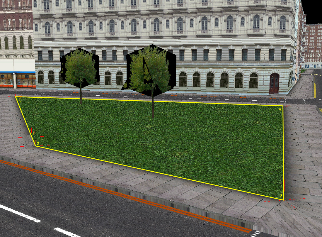
The triangle attributes are, in fact, an entire family of attributes. Eight different attributes can be used depending on the number of vertices the surface requires. Attribute 0x30 is the most general one, this can handle any number of vertices. Attributes 0x31 - 0x37 are limited to 1 - 7 triangles respectively. Attribute 0x31 requires three vertices, attribute 0x37 requires nine vertices.
Roads
In a racing game, the roads are one of the most important features. There are several geometric primitives for defining roads, this section describes them.
Roads without sidewalks
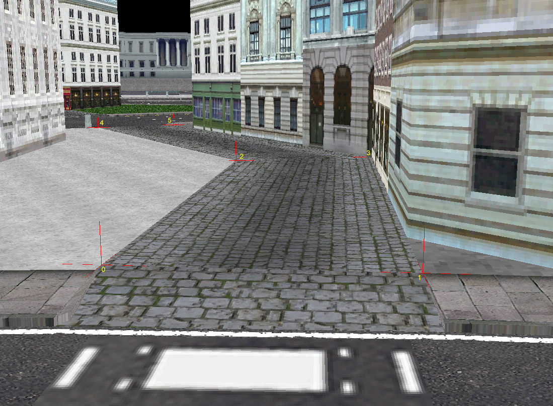
For walkways and narrow alleys without sidewalks the family of attributes 0x10, 0x11 - 0x17 are used. These attributes are defined by pairs of vertices, cross-sections of the road.
Roads with sidewalks
The most common roads in an MM2 city are the ones with sidewalks on both sides. These are easily defined using cross-sections of the road. Attribute family 0x00, 0x01 - 0x07 are attributes to use depending on the number of cross-sections in the particular road segment.
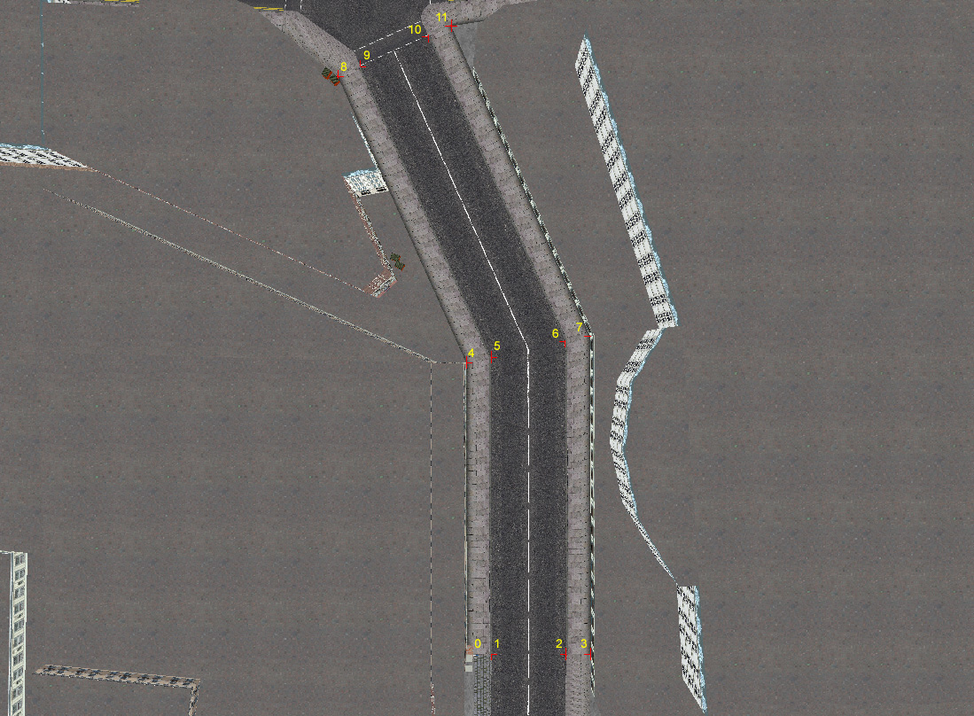
The vertices in each cross-section are organized like this: First comes the vertex defining the position of the outer edge of the left sidewalk, then follows the outer edge of the left road surface, the outer edge of the right road surface and finally the outer edge of the right sidewalk. MM2 automatically renders the vertical sides of the sidewalks and the road surface vertices are expected to be located 15 cm below the sidewalk vertices.
This type of roads use three textures. The texture attribute points out texture n, this texture is used to render the road surface. This texture is mirrored along the center line of the road. The sidewalks are rendered using texture n + 1 and texture n + 2 is the texture used across the entire road in the lowest LOD, or level of detail, of the road segment.
Divided roads
Some roads, typically wide avenues or highways, have a divider along the middle, separating the drive ways. In MM2, such roads are defined by the attribute family 0x40, 0x41 - 0x47.
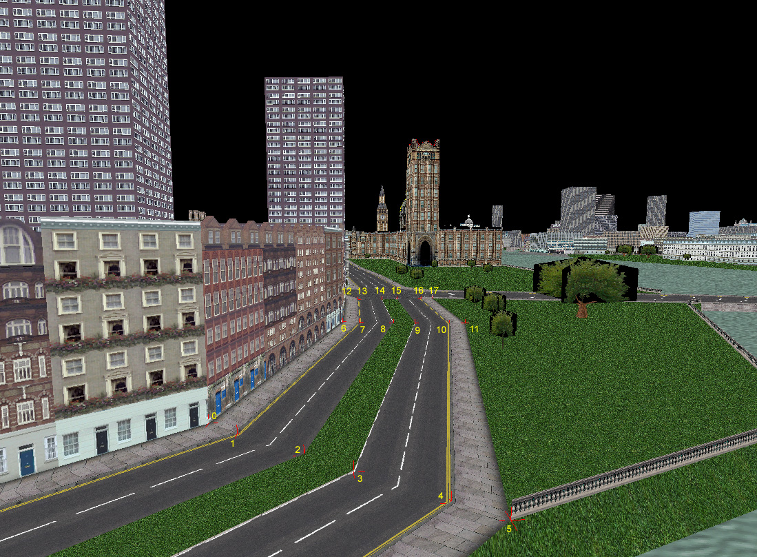
The vertices in each cross-section are organized like this: First comes the vertex defining the position of the outer edge of the left sidewalk, then follows the outer edge of the left road surface, the inner edge of the left road surface, the inner edge of the right road surface, the outer edge of the right road surface and finally the outer edge of the right sidewalk. MM2 automatically renders the vertical sides of the sidewalks and the road surface vertices are expected to be located 15 cm below the sidewalk vertices.
The road surface and sidewalks are rendered in the same way as the road with sidewalk attributes.
Divider type
Several types of dividers can be created by using various parameters to the divided road strip attributes. First we have a flags parameter, the flags paramter is divided into two parts, it is currently not 100% clear how many bits belong to which part, but the examined road attributes in SF and London indicates that at least the two lowest bits of the flags parameter is a divider type.
In addition to the flags parameter there is also an extra texture reference and a value parameter. These are used differently depending on the divider type.
- 0: Invisible
- No divider is rendered, but the bound is there.
- 1: Flat
-
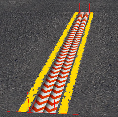
A flat divider is in the same height as the road surfaces, the value parameter defines how many times the texture is repeated across the divider. - 2: Elevated
-
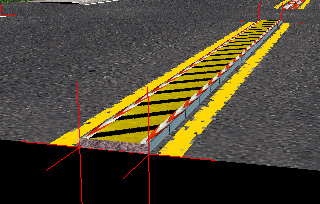
The value parameter specifies the height of the divider and the width of the side strips. - 3: Wedged
-
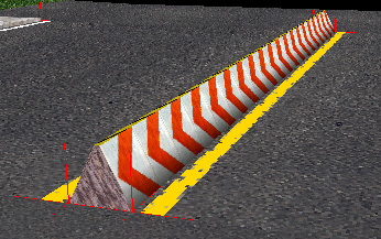
A wedged divider is always one metre high. The top of the sloping sides are always 0.5 metres towards the center of the road from the given divider vertices. The remaining width between the two divider vertices are filled by a flat top strip.
Only two flags are known, besides the two type bits, those control the closing of the short-ends of the divider. Bit seven closes the divider at the start and bit eight closes the divider at the end. The first section of a divided road should close it's start, the last section should close it's end. Intermediary sections shouldn't close anything.
All dividers in these examples use the same textures:
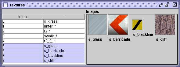
The texture index, n, in this case n = 5, points to the
texture used for the sides of an elevated divider. n + 1 is used for
a flat divider, the sidestrips of an elevated divider and the sloping sides
of a wedge divider. Texture n + 2 is used for the center strip of an
elevated or wedge divider. Finally, texture n + 3 is used to close
the dividers.
Tunnels and railings
It is easy to define tunnels and railings following road segments in MM2. Just precede the road attribute with attribute 0x4b.

This attribute has several parameters allowing for many different types of tunnel and roadside railing set-ups.
- 0: Left wall
- 1: Right wall
- 2: Wall
- 3: Flat ceiling
- 4: Close start left wall
- 5: Close end left wall
- 6: Close start right wall
- 7: Close end right wall
- 8: Subdivided ceiling
- 9: Offset start left wall
- a: Offset end left wall
- b: Offset start right wall
- c: Offset end right wall
- d: Subdivided inner walls
- e: Thick walls
- f: Unknown
For intersections inside tunnels, use attribute 0x48 instead. This attribute has not been 100% explained yet.
Intersections
When defining intersections, a number of specific attributes are used.
Road surface
The road surface in an intersection is usually defined by a triangle fan. Not the regular triangle fan, but by an attribute of the family 0x29 - 0x2f. It is unclear if this family has a general variant that can handle any number of vertices, but if it does, this attribute should be 0x28. Attributes 0x29 to 0x2f are for one to seven triangles, three to nine vertices respectively.
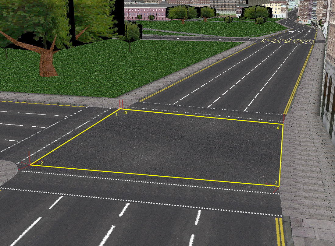
These attributes use texture n.
Sidewalk
Sidewalks are defined by a number of degenerated cross-sections. The attribute family 0x08, 0x0a - 0x0f are seven different attributes used depending on the number of cross-sections. Attribute 0x08 is for any numbre of cross-sections while 0x0a - 0x0f are for two to seven cross-sections respectively.
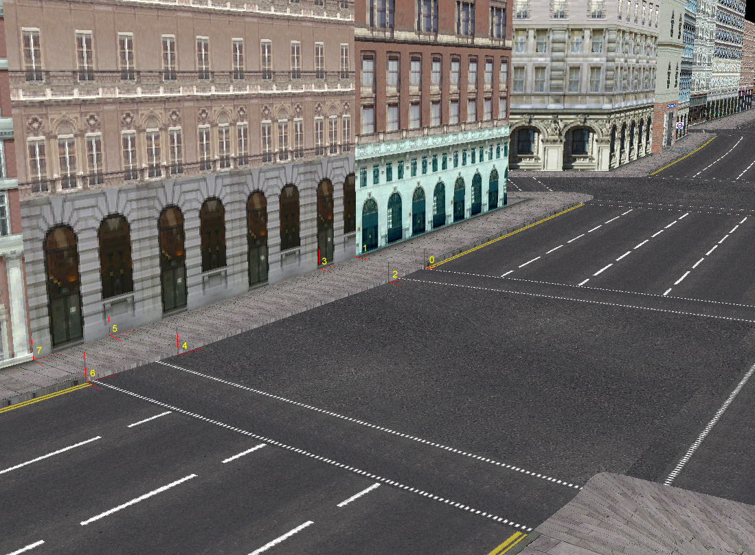
The cross-sections are constructed like this: First comes the vertex on the road surface and then comes the vertex on the outer edge of the sidewalk. The road vertex is expected to be 15 cm below the outer vertex.
There are two special cases of sidewalk strip attributes. The attribute 0x0a is also used to define the end section of a sidewalk that ends.
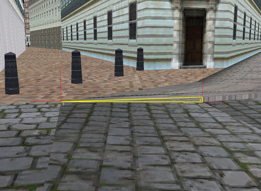
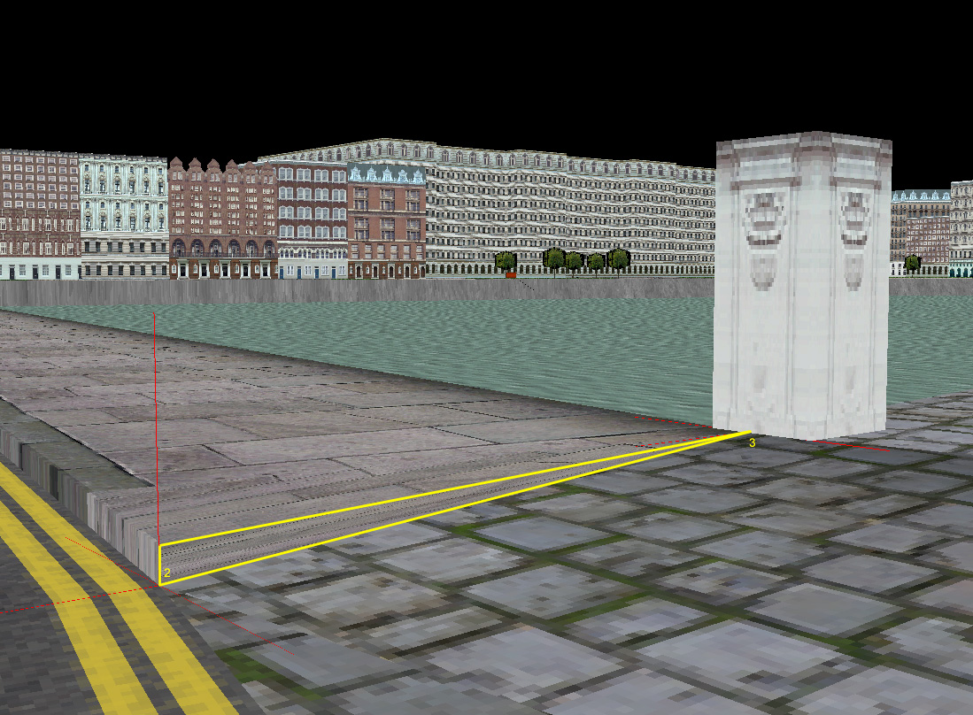
This is indicated by setting both vertices in the first cross-section to zero or one. Zero or one indicates what side of the resulting triangle should be rendered. As usual, the first vertex is the road surface vertex, thus it is expected to be 15 cm below the second vertex representing the outer edge of the sidewalk.
Sidewalk attributes use texture n + 1.
Crosswalks
A crosswalk is defined as a two-section triangle strip in attribute 0x24. Four vertices defines it's shape and location.
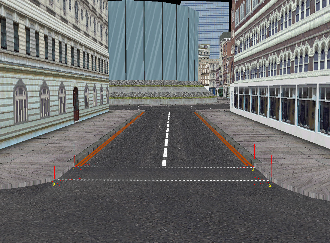
Crosswalk attributes use texture n + 2.
Buildings
In PSDL, buildings with flat, textured facades can be made using a group of attributes. A block can have any number of facades, enabling complex structures. But if the facade itself requires a complicated 3D structure it should be modeled and stored in a PKG file and placed with INST. For more information about that, refer to the INST section.
Facade bounds
Each facade has a bounding box. Attribute 0x3c defines the extent of the complete wall, from ground floor, or even basement, to the roof.
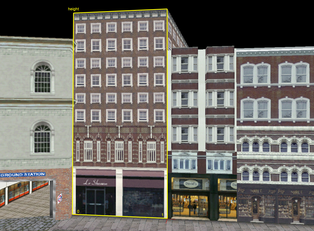
The facade bound attribute follows the ground as defined by the two vertices for the bottom left and bottom right corners of the wall. The height of the wall is defined by a reference into the list of heights. The top side of a facade is always perfectly horizontal.
A facade bound attribute has one additional parameter. This defines the angle for the normal of the wall. This is used to determine the amount of light that hits the wall and thus giving a simple but effective lighting effect. The angle is an integer in the interval 0-63, allowing to define the angle in steps of 5.625 degrees.
Ground level facades
The ground floor must follow the ground surface at the bottom, even if the ground surface isn't perfectly flat. Attribute 0x1c allows this. The 0x1c attribute is defined the same way as the facade bound. But instead of the angle of the normal vector, this attribute has a parameter with a function that has yet to be uncovered.
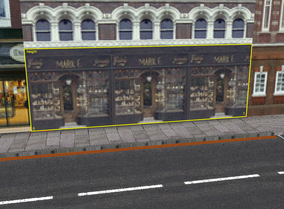
The top side of a facade is always perfectly horizontal and the facade attributes use texture n.
Facades
Most facades are perfectly horizontal, both at the bottom and the top-it would be awkward with sloping floors inside. In MM2, the standard facade is defined using attribute 0x5e.
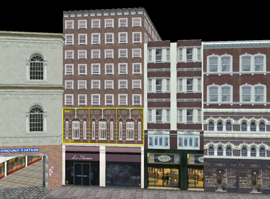
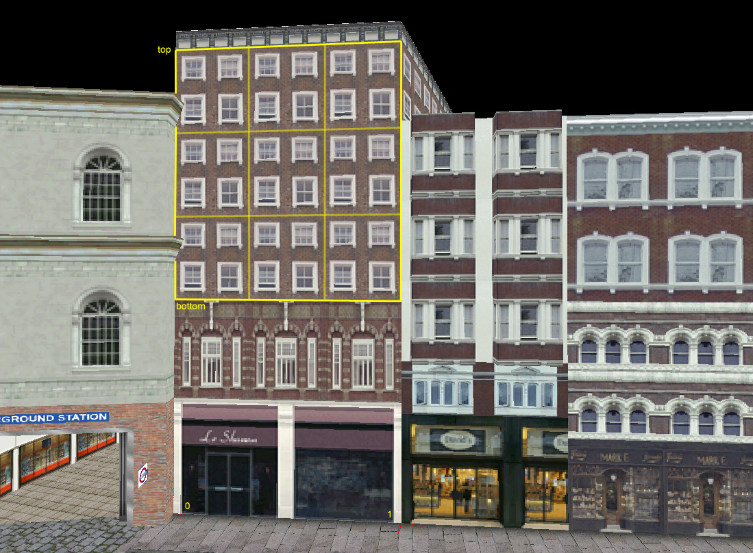
This attribute still defines the left and right side with two vertices, but the y-component of these vertices are not used. Instead heights from the height list are used for the y-component of both the bottom and the top.
The facade attribute uses texture n and it has two parameters controlling the scale of the texture. xRepeat and yRepeat indicate the number of times the texture should be repeated horizontally and vertically. This provides a useful function that allows for easy creation of several, identical floors with just one facade attribute. The images show one facade with xRepeat=3, yRepeat=1 and one with xRepeat=3, yRepeat=3.
Roofs
Rooftops in MM2 are always flat. They are defined by the triangle fans in attribute family 0x60, 0x62-0x67. The vertices of these attributes are organized in the same way as the regular triangle fans, but these attributes also have a reference to a height in the height list. This height is used to replace the y-component of the vertices.
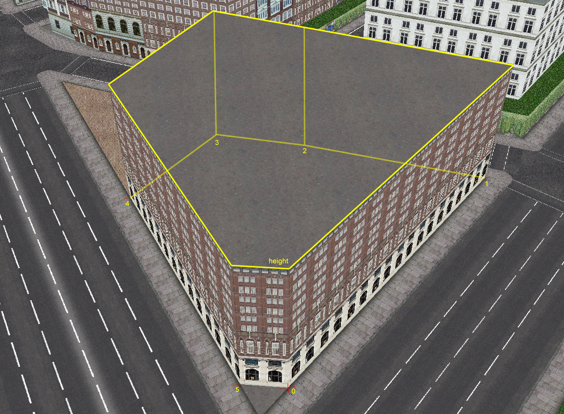
Roof attributes use texture n.